Managing a modern home efficiently is no longer just a luxury — it’s becoming a necessity. From controlling lights and appliances to enhancing security and reducing energy bills, homeowners are seeking smarter, more automated solutions. Unfortunately, many commercial home automation systems are expensive, complex, and locked into proprietary hardware.
To solve these challenges, we’ve developed an Arduino‑Powered Smart Home Automation System — a cost‑effective, customizable, and scalable solution that puts complete control of your home at your fingertips. Using the versatile Arduino microcontroller, this system allows you to automate lighting, fans, appliances, and even integrate security sensors — all controllable via smartphone, voice assistants, or scheduled routines.
At the heart of this project is the Arduino Uno or Arduino Mega, paired with a Wi‑Fi module (ESP8266 or ESP32) for seamless internet connectivity. The system communicates with a mobile app (Blynk IoT or a custom‑built interface) to let you monitor and control your home from anywhere in the world.
Whether you’re a DIY enthusiast, a tech‑savvy homeowner, or someone looking to reduce energy consumption, this project offers flexibility, reliability, and peace of mind.
Working of Arduino Smart Home Automation System:
The Arduino is programmed to control each connected device via relay modules. The Wi‑Fi module connects to your home network, enabling remote access through the Blynk IoT app or a custom mobile application.
Users can:
- Monitor temperature, humidity, and device status in real time.
- Turn lights, fans, and appliances ON/OFF manually or on a schedule.
- Automate devices based on sensor readings (e.g., turn on fan if temperature exceeds a set value).
- Receive alerts for motion detection or unusual activity.
Components Used in Arduino Smart Home Automation Project
| Component | Description |
|---|---|
| Arduino Uno / Arduino Mega | Main controller for processing commands and controlling devices. |
| ESP8266 / ESP32 Wi‑Fi Module | Enables wireless communication with the IoT app. |
| Relay Modules (5V) | Switches high‑voltage appliances like lights, fans, and sockets. |
| PIR Motion Sensor | Detects movement for security automation. |
| DHT11/DHT22 Temperature & Humidity Sensor | Monitors indoor climate for automated fan/AC control. |
| Light Dependent Resistor (LDR) | Automates lighting based on ambient brightness. |
| Blynk IoT Platform or Custom App | Provides a mobile dashboard for control and monitoring. |
| 5V Power Supply / Adapter | Powers the Arduino and connected modules. |
Smartphone Control of the System
Using the Blynk IoT app, you can:
- Control devices with buttons or sliders.
- View live sensor data (temperature, humidity, motion status).
- Set timers or schedules for each appliance.
- Get push notifications for security alerts.
Example App Interface:
- Button: Light ON/OFF
- Button: Fan ON/OFF
- Scheduler: Appliance Timers
- Display: Temperature & Humidity Readings
- Alert: Motion Detected Notification
Custom App Option
For advanced users or businesses, we offer:
- Integration with camera feeds or advanced analytics.
- Brand‑specific UI/UX design.
- Multi‑room or multi‑building control.
- Offline control via Bluetooth.
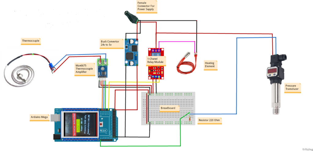
Circuit Diagram of Arduino Smart Home Automation Project:
Arduino Code Smart Home Automation Project:
#include <Adafruit_GFX.h>
#include <MCUFRIEND_kbv.h>
MCUFRIEND_kbv tft;
#include <TouchScreen.h>
#include "max6675.h"
#include <PID_v1.h>

//----------------------------Thermocouple Declaration-----------------------------
int Temp_Threshold = 10;
int thermoDO = 19;  //SO
int thermoCS = 18;  //CS
int thermoCLK = 17; // SCK
MAX6675 thermocouple(thermoCLK, thermoCS, thermoDO);
const int Relay_pin = 21;
int previousTime;
double setPoint, outputVal;
int TEMP_READ_DELAY = 500;
double temperature = 0, last_temperature, last_temperature2;
unsigned long lastTempUpdate; //tracks clock time of last temp update

//----------------------------PID Parameters--------------------------

//------------------------------------------
int Experiment_Time = 12;   // In minutes
int Reading_Time = 5;       //In Seconds
int Current_Temperature = 30; // You can mention the room temperature here to speed up the test
float Heating_Rate = 0.1, s;    // Heating Rate is 1 degree pe 4 seconds or 0.25 degree per second
//-----------------------------------------


double Setpoint, Input, Output;
double Kp = 200, Ki = 5, Kd = 1;
PID myPID(&Input, &Output, &Setpoint, Kp, Ki, Kd, DIRECT);
double seconds;
int WindowSize = 2000;
unsigned long windowStartTime;
unsigned long lastPrint;
int last_Seconds, Seconds, i = 0, S;

//----------------------------Pressure Sensor Declaration--------------------------
#define Pressure_SENSOR_PIN  A8 //Pressure Sensor Pin
float  current, volts;


//----------------------------2.4" TFT LCD Pins Declaration-------------------------
#define MINPRESSURE 10
#define MAXPRESSURE 1000
const int XP = 8, XM = A2, YP = A3, YM = 9;  // 240x320 ID=0x7789
const int TS_LEFT = 69, TS_RT = 959, TS_TOP = 48, TS_BOT = 916;
TouchScreen ts = TouchScreen(XP, YP, XM, YM, 300);
Adafruit_GFX_Button start_btn;
int pixel_x, pixel_y;  // Touch_getXY() updates global vars

#define BLACK 0x0000
#define BLUE 0x001F
#define RED 0xF800
#define GREEN 0x07E0
#define CYAN 0x07FF
#define MAGENTA 0xF81F
#define YELLOW 0xFFE0
#define WHITE 0xFFFF


bool sprinklerActivated = false, start = false, min = true,
     flag1 = true, flagP = false, flagT = false, flagSprinkler = true, Heater = false;
unsigned long startTime = 0, Start_time;
unsigned long elapsedTime = 0;
double pressure = 0, last_pressure, last_pressure2;
unsigned int minutes = 0, last_minutes = 0;
unsigned int  last_seconds = 0;


bool updateTemperature() {
  if ((millis() - lastTempUpdate) > TEMP_READ_DELAY) {
    temperature = thermocouple.readCelsius(); //get temp reading
    lastTempUpdate = millis();
    return true;
  }
  return false;
}


void setup(void) {
  Serial.begin(9600);
  windowStartTime = millis();
  pinMode(Relay_pin, OUTPUT);
  uint16_t ID = tft.readID();
  if (ID == 0xD3D3) ID = 0x9486;  // write-only shield
  tft.begin(ID);
  tft.setRotation(0);  // PORTRAIT
  tft.fillScreen(BLACK);
  digitalWrite(Relay_pin, LOW);  // Turn OFF heater
  Serial.println((String)"\tSystem ON");

  //tell the PID to range between 0 and the full window size
  myPID.SetOutputLimits(0, WindowSize);
  //turn the PID on
  myPID.SetMode(AUTOMATIC);

}
Applications
- Shops and small businesses.
- Residential homes.
- Office automation.
- Smart classrooms.
- Hotels and guest houses.
Future Upgrades
- Voice control via Google Assistant or Amazon Alexa.
- Energy consumption monitoring.
- Integration with IFTTT for advanced automation.
- Security camera streaming.
- AI‑based automation for predictive control.
Need This Project?
If you need Fire Sprinkler Testing Device Project with or without Modifications or Customization then you can contact us through WhatsApp. We can deliver you this Project in the Following Ways.
Project Code Only:
we can provide you Project Code along with Zoom Assistant, through Zoom meeting for Setup of this Project or any other Arduino Project of your need.
Fully Functional Project with Hardware/Components Shipment:
if you can not make this project yourself then you can use this option. We will assemble the Project and will ship it to your Doorstep with Safe Packaging.
Learn More about the services we offer.